Search This Blog

Thursday 2 May 2019

Breaking Revit 2020's Elliptical Wall Function

It has been a while: 5 months to be honest. Life, work happens and we were fortunate enough to start the year running at full speed. None the less, with the release of Revit 2020 a new wall modelling function was added: Elliptical walls. 

This entry will see what can be achieved with wall ellipses and how (if) we can break the function. 

Elliptical walls are created in a similar fashion to circular walls: In two section sections. One will notice that when trying to join walls drawn from the major axis' start and end (We will get to making our walls snap to the wall end points further on in the blog post) only one side joins cleanly. When joining the right side, the left unjoins itself and visa versa. However, disallowing the joining condition on both vertical walls and manually joining the geometries solves this problem.


Creating a partial elliptical wall behaves in a similar fashion, with the exception that one can snap to the elipse's end and mid points, and that one of the vertical wall's ends join automatically. The other will have to be manually joined. 

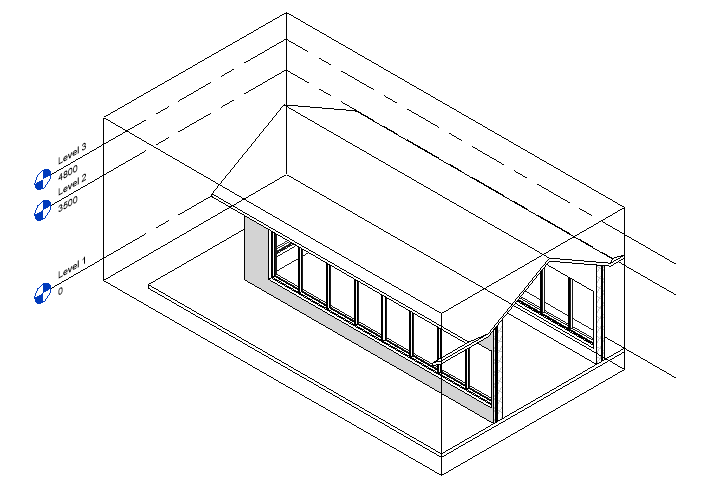
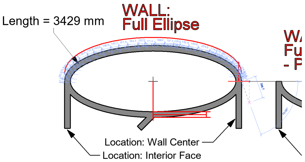
An interesting observation is that one can not snap to the partial ellipse's start corner or mid point when it forms part of a full ellipse. Thus, should you require something similar to the image below, detail lines will be your friend (albeit not perfect as one cannot snap to the wall)

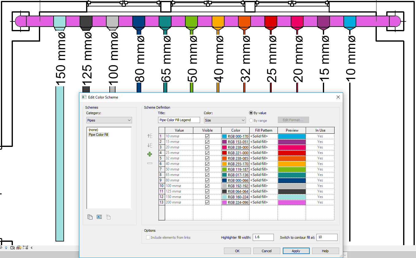
Regarding dimensioning: Arc Length dimensions do not work with elliptical forms. Even when creating a detail line in an ellipse, one cannot select the line at all. 

For openings, the only opening which can be added is a rectangular wall opening. No profile edits can be made on these wall forms. As a side note, no decal can be placed on an elliptical wall form. 

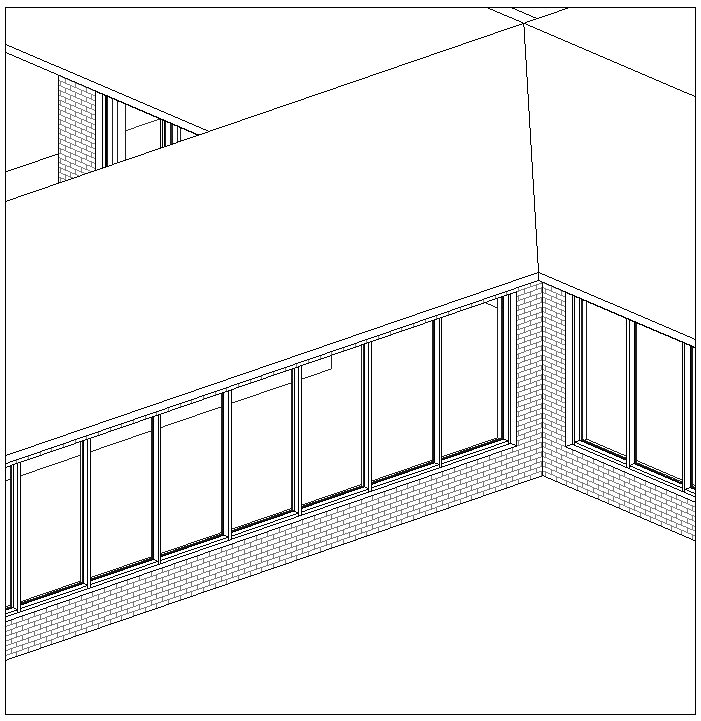
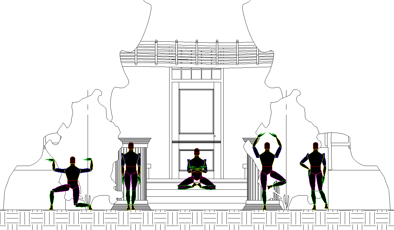
What about adding wall hosted components to the wall? As per adding a door or window to a curved wall, there will be discrepancies.


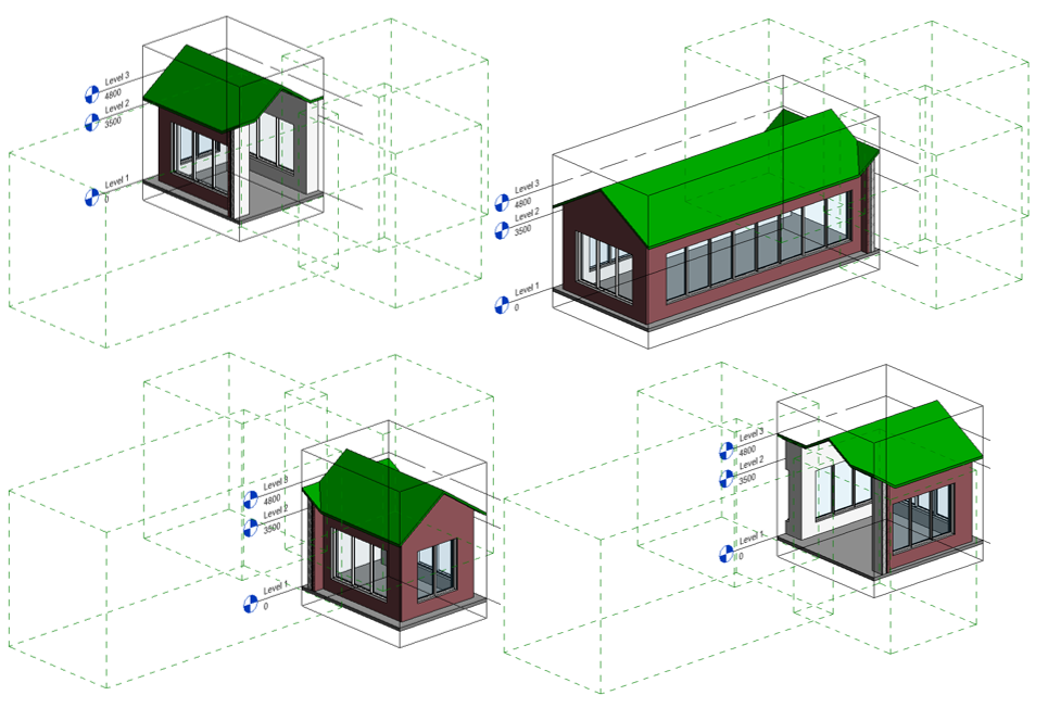
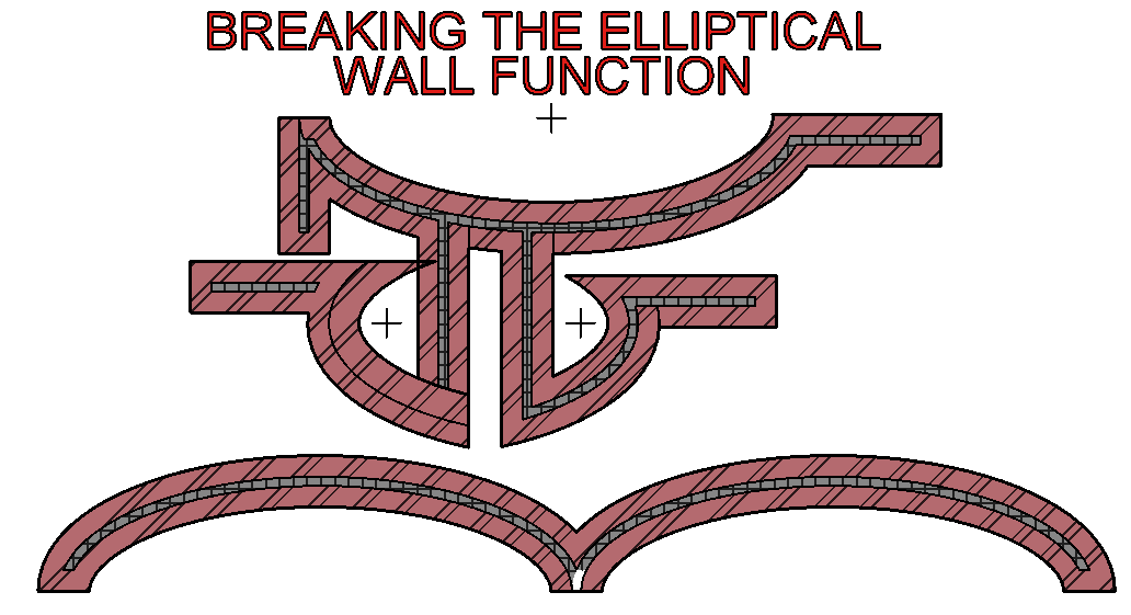
Where the elliptical wall falls short, is with wall joins. As can be seen from the examples below (Yes, some are extreme) the joining conditions are not perfect. What is interesting though, is the behaviour to the bottom left of the image below. Notice the cavity wall freaking out and losing its air space layer.  
Even with the observations highlighted in this entry, I am very glad that we have this wall creation option. Any improvement is a timesaver in my books. 

Have a good week, folks! Until next time. 

Saturday 22 December 2018

Farewell 2018, Hello 2019!

As 2018 is coming to a close and has given us some amazing architecture, engineering and construction projects all over the world, I can only hope that 2019 will up the ante even further.

South Africa has had a number of amazing projects reaching completion in 2018, none of which I will highlight in this post. Why? The reasoning is simple: Only a few of these projects have reached the papers, magazines, blogs and the like. I can promise that, if only looking at my current client base, the sheer amount of quality designs will make choosing the best impossible. Do yourself a favour and Google some AEC inspiration on the "dark continent" 

There is however one project located just outside of Worcester, Western Cape which still amazes me. Bosjes Chapel, designed by Steyn Studio based in London (Coetzee Steyn is a South African by birth after all), completed in 2017. Just have a look at this picture which simply just does not justify physically being there yourself.

As quoted directly from Steyn Studio's website, let the team speak for themselves: 

" The site is surrounded by majestic mountains with a grand scale which adorned the area with the nickname of 'Little Switzerland'. Typically Cape Dutch Manor houses set up dialogue with these types of environments, as found in Stellenbosch and Cape Town. With the immediate context of the site, the valley is 'held' either side with two mountain ranges which sets up a spatial dialogue at a grand scale which occurs on a 'micro' level between the Manor House development node and the Chapel development node; across the vineyards and gardens.

The chapel development reflects, in microcosm, one half of what already exists at the scale of the valley as a whole in terms of its sculptural relationship, as does currently exist between the Manor House and the Waaihoek Mountains. The development profile, architectural form and massing responds sculpturally to the natural configuration of the mountain backdrop. 

Similarly, the text of Psalm 36:7 is also considered as an important informative from a poetic point of view, and its interpretation, architecturally, as a structure which 'floats/glides' and has motion, although physically static. 

In order to achieve the visual 'lightness' of the roof, the structure has to be simple, unifying and as structurally efficient as possible. It was therefore decided that the roof can also become the walls/columns; its own supporting structure. To realize this we investigated parabolic/hyperbolic arches and surfaces; and its use in thin shell concrete structures.

This translated into the sculptural form which emulates the surrounding mountains as well as the poetic motion sought. This lightness & motion is further emphasized by means of the interpretation of the baroque 'holbol' gable in the edge profile and the roof shape. The main characteristic of a 'holbol' gable is that of the combination of outward and inward curvatures which results in a series of 'peaks' and 'valleys' within the roof itself. 

Similar to the Mission Churches it has no vertical elements and the form is generally horizontal. As with the gables present on these churches, the identifying element on the Chapel is that of its roof and its shaped edges. Apart from investigating the local history of the farm we also looked at Moravian Missionary Stations as inspiration. The aim of the chapel is also to reflect the following qualities present in these historic missionary churches of Mamre, Elim and Wupperthal: 
- Utilitarian simplicity of its plan as an assembly space 
- Scale
- Cultural reference 
- Tranquility of its white lut interiors
- 'Tactileness' of its undulating whitewashed walls

However, whereas these churches are mostly inward looking and spiritually reflective, the proposed chapel is to be a more 'open' space which invites in, as well as expands its intimacy to the valley and mountains beyond, raising the awareness of God's creation in the immediate surroundings. " 

 Psalm 36:7 in Afrikaans: "U geregtigheid tot op die hoogste berge, die reg wat U spreek, tot in die dieptes van die see. U sorg vir mens en dier, o Heer"

May all Revit Recess readers have a blessed Christmas and wonderful new year. 2019 will have a number of new and exciting adventures in store for us all.

Monday 10 December 2018

Stacked Walls: Alternative Uses

Stacked walls are often one of the lesser used functions in Revit. It does have its own pro's and con's, but in this entry, we will look at what one can achieve using stacked walls. This is not necessarily a how-to post, it is more of a "what can we do with stacked walls"  post.

None the less, let's get started

The basic composition of this stacked wall is 9 Generic 600mm walls with a height of 250mm. Stacked walls does however require at least 1 section of variable wall, which forms the 10th piece of wall.

I quite like the fact that due to a stacked wall being just that: a wall, the normal wall editing functionality still applies. Selecting the stacked walls and pressing space bar will flip the walls' orientation.

Editing wall joins only affects the variable layer of the stacked wall.

Wall profile edits will allow you to edit the top and bottom of the stacked wall - Think base and top constraint. Any closed profile sketched inside of the outer profile boundaries will create a cut out.

Attaching the top of the stacked wall to a floor and roof also works. Note that the variable layer only attaches to the roof.

A wall is a wall and thus the typical architectural and structural column behaviour still applies when adding those "through" the wall.

Wall sweeps and reveals can also be added to the stacked wall.

When I tested the updating of the stacked wall to a conceptual mass, I noticed something interesting: The "Update to face" icon in the ribbon wasn't there anymore. Seeing that I was using Revit 2019 for this entry, I noticed that the latter has been replaced with a "Remake" icon in the options bar.

Using stacked walls, we can still host elements on the faces of the wall itself, like wall-based or face-based lighting fixtures.

Have a great week, folks!

Friday 26 October 2018

Multiple Instances Of One Project Link In A Federated Model

"Anything that is worth teaching can be presented in many different ways. These multiple ways can make use of our multiple intelligences." - Howard Gardner

Imagine working on a project where there are multiple buildings/rooms/spaces which looks exactly the same, but in different locations, elevations or orientations. Many think that each one of those buildings/rooms/spaces must be handled as separate project files, which would then be linked into the Master Project file (Typically the Shared Levels and Grids Project, containing the topography)

However: There is an easier way of doing this

In this example, two buildings were created, each in their own project file. Multiple instances of these buildings were placed in different locations, at different elevations and orientations within a Federated Project file. By entering the Shared Site functionality of a specific link, notice that one can record the position of this linked file's INSTANCE. This is a very important concept to remember. Even though we are working with one file, changing this setting will only affect the selected instance/s.


Notice that we can create multiple positions of the same linked file, thus being able to place multiple instances of the same building in our project, and record those unique positions.

The above becomes quite important when other parties need to work on/with your project. They would link the Topography, and each individual link into their project (In this case we use a Structural Engineering model as an example). When entering the Shared Site functionality, we can control that Building A must be linked into both the Unit A1 and Unit A2 positions. Similarly, Building B must be linked into both the Unit B1 and Unit B2 positions.

Should anything change within the linked files, it will update automatically, retaining the position, elevation and orientation.

Even your schedules, provided that you have entered the correct non-graphical information into your linked files and linked instances, will show the correct information.

Seeing that it is Friday, how about a bit of philosophy?
Irrespective of whether you agree with Howard Gardner's theory at the start of this blog entry or not (Intelligences versus Aptitude versus Personality Traits), I do believe that Education and Training needs to adapt to the ever changing times, industries, atmospheres and technologies.

People's behaviours and perceptions also needs to drastically change. Don't get me wrong, this is not a rant. However, I came across a very thought provoking Ted Ed talk by the former host of Dirty Jobs, Mike Rowe: Learning From Dirty Jobs.

Yes Mike, I got a lot of things wrong too

Friday 12 October 2018

Revit 2019 - Precast Add-in


"Better Quality, More efficiency, Unbounded Creativity" - blogs.autodesk.com


I recently played around with the Precast Add-in for Revit 2019, and I must say that I had some fun in doing so.

Trying to see if I could "break" the add-in, I created a ring's head using structural walls

These walls were split through the Precast add-in, providing the results below:

Reinforcement was automatically added to each splitted part through the add-in as well

Selecting the Shop Drawings command, Revit generates Assembly views, complete with Sheets and Schedules and places it on each part's sheet. Minor tweaking will need to be done regarding the placement location of the views on the sheets.

Have a great weekend folks!

Friday 21 September 2018

3D View Manipulation Using Scope Boxes - Revit 2019

Something I do love about new releases of Revit, and even with new Service Pack updates, is that we often find new features which are not part of the official new features lists. Similar to the previous Revit Recess post: Revit 2019 Colorfill Legend Visual Style, we have another exciting new feature which allows us to crop a 3D view with a scope box.

Let's start this entry by looking at the various ways in which we can manipulate the extents of a 3D view:

Method 1: View Crop Region - Pretty much self-explanatory

Method 2: Section Box - A manual method of isolating a specific area of your model, manipulating the section box extents by pushing and pulling the section box sides. The biggest drawback to this method is that the size and position of the section box is not saved. In other words, if you meticulously position and size your section box, turn it off and turn it on again, the section box extents will be around your entire project.

Method 3: Selection Box - My go-to method for automatically sectioning a 3D view according to selected objects. A "Bread-and-Butter" command along with Trim and Align.

Method 4: Scope Box - Revit 2019 now allows us to apply a scope box to a 3D view. This is game changer, especially when working on very large and complex projects, where a lot of time has been spent setting up specific positions for scope boxes on plan views. Very nice feature.

Have a great weekend, folks! For the South African readers of Revit Recess, enjoy Heritage Day on Monday!

Monday 10 September 2018

Revit 2019: Colorfill Legend Visual Style

Revit 2019 has provided us with 2 great Colorfill Legend functions called "Highlighter Width" and "Switch to contour fill at" for Piping.

From the image below, notice how the graphics for pipes looks. The default setting for "Highlighter Width" is 1.6, which controls the thickness of the colorfill lines. The default setting for "Switch to contour fill at" is 152.4, which means that any pipe with a size of more than 152.4 (In the example) would not have a border, but rather be filled with colour. 


When changing the "Switch to contour fill at" option from 1.6 to 0.5, the border lines for the piping are a lot thinner.

Similarly, changing the above option to 3, results in a much thicker border lines

Changing the "Switch to contour fill at" option to 50, will ensure that all pipes larger than 50mm will have a solid fill instead of border lines.  

And lastly, changing the above option to 10 will ensure all pipes larger than 10 will have a solid fill. 

These new functions could make isolating certain properties on piping a lot easier, without having to set up multiple filters to achieve a specific visual style. 

Have a good week, folks!

Tuesday 21 August 2018

Revit Artistry


"In the big picture, architecture is the art and science of making sure that our cities and buildings fit with the way we want to live our lives" - Bjarke Ingels


For quite some time I have wanted to create an art piece, a sculpture, natively in Revit. Some of you might be thinking, "just because you can do something, does not mean you should"; I whole heartedly agree with this statement. However: Being able to 'fully' utilise any piece of software, you have to hone your skills regularly, you have to broaden your mind to what else is out there. In other words, what can I create that will challenge me? The last physical sculpture I have ever made was in kindergarten where we were given play dough and straws. I think I need to remedy this.    

In the meantime, a digital sculpture will have to do. I sourced an image from the internet and traced over it using the spline command (TIP: Save yourself hours and download an Auto-Clicker program). These shapes were extruded and a random void cut layout was added.

I searched for a paint splatter image on the internet and thought that the image below would look interesting when being used as a decal image.


I'm quite satisfied with the end result:

Thursday 16 August 2018

Release: Revit 2019.1

Earlier today, Revit 2019.1 has been released and it does have some nice new features for us to explore (Revit Blog) . In short, here are some of the key new features and improvements:

* Revit Home - Revit Home is a new user experience that modernizes the way you access, store, and share project information.

* Site Collaboration with Civil 3D - Site Collaboration is a Revit 2019.1 new feature that introduces unprecedented interoperability between Revit and Civil 3D New workflows will help both save time and improve accuracy when you are transferring site information and project location data between project teams.

* Support IFC Links from BIM 360 with Desktop Connector - With Revit 2019.1 IFC files can be linked in Revit using Desktop Connector and they will maintain their links. This feature will open doors for new IFC collaborative workflows.

* Free Form Rebar Aligned Distribution - In Revit 2019.1 the Free Form Rebar tool can now be used to create rebar sets with planar bars distributed along the faces of a structural element and aligned to a distribution path.

* Move Pattern on Top of Wall - With Revit 2019.1 you have greater control over the look of a wall at every visible surface and enhanced wall control. You can now drag, rotate and align a model pattern on a painted top surface of a wall such that you may adjust the pattern tile location on all faces of a wall for highly controlled alignment.

* Import Double Fill Patterns - With Revit 2019 you got double-fill patterns. Now with Revit 2019.1, importing patterns from AutoCAD to Revit is easier and requires less management. When importing a double fill pattern (a hatch with a background color) from AutoCAD to Revit, you will now see the background color on import. 

* Improved Work with Perspective Views - Revit 2019.1 includes a set of enhancements to perspective views that dramatically improve the modeling process in 3D views.

* Section View Align and Snapping - In Revit 2019.1 you can use the Align command to select the line for a section view and use it as the reference for alignment or as the object to align. 

* Resizable Dialogs - In response to customer requests submitted via the Revit Ideas page, Revit 2019.1 new features include the ability to resize the Go To View dialog and the Add View to Sheet dialog. 

Have a great week, folks!

Thursday 19 July 2018

Awesome Entourage in 5 Seconds

“We have so much time and so little to do. Strike that, reverse it.” — Roald Dahl

The value of previous Autodesk University classes are highly underrated and underused. I found a AU 2016 class by Marcello Sgambelluri called: "More Families in Motion: New and Exciting Methods That Make Your Revit Families Move". Based upon the information shown in this class, I was able to create some awesome 2D entourage families with minimal input, in any pose that I required. 


As we all know, visualising data enables one to make more informed decisions - Verifying the ergonomics of a space, as an example. After all, whatever few seconds we can spare during work time, is less time we have to spend stuck in traffic.


Due to the speed and ease of changing the entourage family's pose, I even created my first Revit stop motion video, just for fun.

Have a great week, folks!

Friday 13 July 2018

Hmmm... I haven't seen this before

"If you learn something new every day, you can teach something new every day." - Martha Stewart 

I came across two functions/properties in Revit recently which I have not noticed before. The first function is quite useful, especially if you tend to prefer right-click properties in Revit. I have checked the previous versions of Revit and it seems that this specific function was introduced in Revit 2017 (Likely the 2017.2 UR): 

In both the family creation environment, as well as the project environment, you are able to directly add a label to a dimension value through your right-click properties, as indicated by the images below. In the family creation environment, you will create a family parameter, whilst in the project environment, a global parameter will be created.


The second function is quite interesting and I have to admit, I scratched my head for a few seconds with this one! When drawing a circle in the Generic Annotation family environment, have a look at the properties panel: You might have noticed the Center Mark Visible option before, which is very useful for alignment and the like. 

However, who has noticed another property field called Filled? If checked, this property will automatically hatch the circle with a solid fill pattern. Try as you might to select this fill without knowing about the option is quite a task!

Have a great weekend, folks!

Friday 6 July 2018

Origami Revit

"Scale allows us to understand the relationship between a representation - a drawing or model - and reality. Being able to draw accurately to scale, and to shift fluidly between scales, is one of the most important aspects of architectural drawing and spatial design." - Portico.Space


Creating Origami models in Revit was easier than I thought. If one remembers the golden rules of Revit family Creation, such as working from a reference image/sketch, creating a Framework, then Testing/Flexing the framework to see if it works, creating origami models in Revit will be a breeze. 

Recreating the swan in the picture above was done in the Conceptual Massing environment. Point elements were placed at corners and areas where folds were made in the origami model. These points were then connected with reference lines.

After the basic framework was created, depth and height was added by raising and dropping the point elements.

Due to reference lines connecting the point elements, it was possible to create surfaces to which materials were added.

Have a great weekend folks!